

Method & Style Wizard
The Method & Style Wizard will automatically generate a first diagram draft based on some user input, following the Method & Style rules defined by bpmessentials.com.
The aim of the wizard is to assist the process designer in the creation of a correct, consistent, appealing and unambiguous BPMN 2.0 model with the help of pointed questions. This concept – known as “BPMN Method & Style” – has been developed by Bruce Silver and itp-commerce ltd. (2007-2014). The goals of this joint venture include:
- Provide BPM training and certification
- Best known for BPMN Method and Style training
- Method and Style
- Goal: “Good BPMN” – process logic should be clear from the printed diagram
- Barriers to “Good BPMN”
- The hierarchical modeling problem
- How to trace process logic easily from parent to child level
- Structural integrity and consistency
- Instance of each activity must have 1:1 correspondence with process instance
- The hierarchical modeling problem
The Method
Following the Example “Car Dealer Order-to-Cash Process”
General Usage
Reset: Clears all values and resets the wizard.
Preview: Generates a preview image of the diagram.
[Bring to front]: Brings the preview window to the front or re-opens it if it was closed. Only works if a diagram preview has previously been created.
Back: Takes you back to the previous step.
Next: Takes you to the next step.
Create: Creates a Visio diagram based on the collected information.
Cancel: Exits the wizard.
Help: Calls this help page.
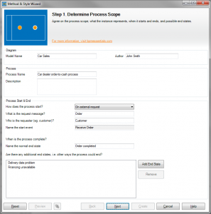
Step 1. Determine Process Scope
Agree on the process scope, what the instance represents, when it starts and ends, and possible end states.
Diagram
Model Name: Name your model.
Author: The author of the model.
Process
Process Name: Name your process, e.g. ‘Order Process’.
Descritption: A short description of the process.
Process Start & End
How does the process start? Choose between “on external request“, “on recurring schedule” or “manually by task performer”.
What is the request message? The request message, e.g. ‘Order’.
Who is the requester? Name the external requester, e.g. ‘Customer’.
Name the start event: Name the start event, e.g. ‘Weekly’ (recurring schedule), ‘Receive order’ (external request).
Name the normal end state: Name the normal, success end state. Use adjective or noun-adjective phrase, e.g. ‘Transaction complete’.
List of additional end states: List alternative, exception end states, e.g. ‘Financing unavailable’, ‘Delivery date unacceptable’.
Following the example:
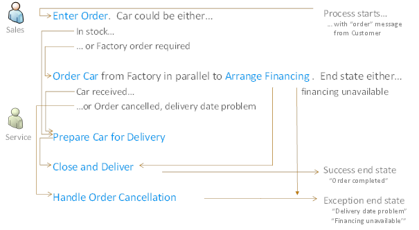
In step 1 we name the diagram as well as the process pool. The trigger that starts the process is an incoming order placed by the customer (external request).
The regular end state is “Order completed”. Exceptional end states may be “Delivery date problem” (customer) or “Financing unavailable”.
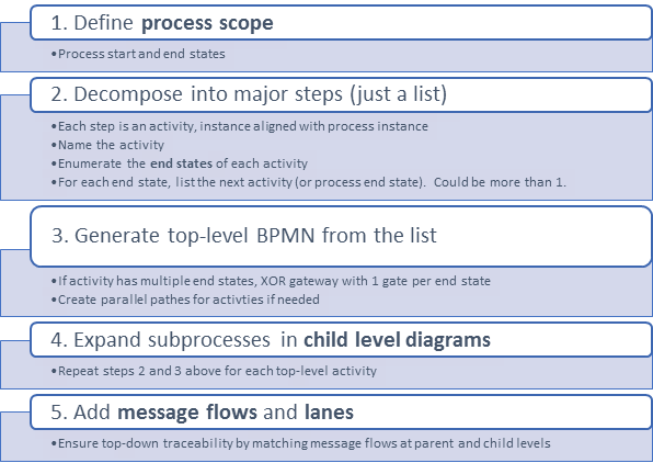
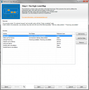
Step 2. The High-Level Map
Enumerate ten or fewer major activities in the high-level map. If the outcome of an activity affects the subsequent path, think about the end states of each activity.
Name the activities using verb-noun phrases, e.g. ‘Finalize order’.
Optionally, you may assign an activity to a performer.
Activities
List major activities and, if necessary, define their possible end states.
- Click on ‘Add Activity’ to add a new activity.
- Select an activity and click on ‘Add End State’ to define the activity’s possible end states. Alternatively, click the ‘End States’ field of an activity.
- You may assign a performer by clicking the ‘Performer/Lane’ field and typing the name of the performer. Performers may be reused using the drop down menu.
Following the example:
In step 2 we define the 7 (+/-2) most important activities of the end-to-end process in a simple list. To obtain the correct granularity for these activities, think of them as sub-processes. For each activity, think of possible ways they could end. If there can be multiple end states that can be reached at the end of the activity, write them down.
If possible, you may also define a swim lane in which the activity will be executed at this point.
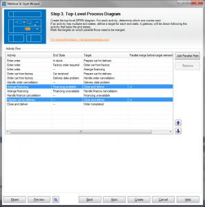
Step 3. Top-Level Process Diagram
Create the top-level BPMN diagram. For each activity, determine which one comes next.
If an activity has multiple end states, define a target for each end state. A gateway will be drawn following the activity that tests the end states.
Mark the targets on which parallel flows need to be merged.
Activity Flow
For each activity, determine which one comes next:
- Choose an activity. If an activity has multiple end states, there will be multiple entries for the same activity with different end states.
- Based on the end state, select which activity comes next in the flow in the ‘Target’ field.
- You may add additional paths by clicking the ‘Add Path’ button. Use this to create parallel flows, for example.
- If the same target is used more than once, i.e. there are multiple paths that lead to the same target, specify if a parallel merge is needed on that target by ticking the column ‘Parallel merge on target?’.
- For easier readability, you may change the viewing order using the up & down arrows. This will have no effect on the actual path generation.
Following the example:
In step 3 we determine the sequence of the activities. The sequence is defined by the activity (first column) and the path for the reached end state leading to the target activity.
If parallel paths need to by merged before one of the target elements, mark them with a check mark in the last column (“Parallel merge before target element”).
Starting point (initial view):
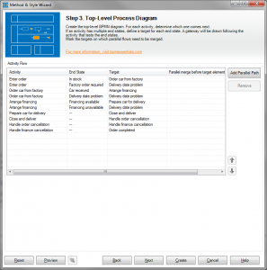
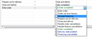
For each activity and corresponding end state you may select the next element in the sequence:
Repeat this step for each entry in the list.
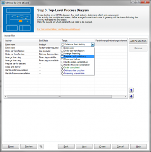
For a better understanding of the sequence you may move activities up and down in the list. In our example, for instance, readability can be improved by moving “Handle order cancellation” and “Handle finance cancellation” closer to the corresponding paths.

Parallel activities:
At the starting point we may have realized that the financing could be executed simultaneously to the other activities, i.e. in a parallel path. Well, how do we create a parallel path?
The first thing we need is a new, additional path, which is created by pushing the “Add Parallel Path” button. A new row will be added to the list. Select the activity from which the additional parallel path originates and determine the target for this parallel path.
In the example, we add a parallel path originating from the “Enter order” activity and connecting to “Arrange financing”. Again, to improve the understanding, you may move the record closer to the corresponding activity.
In order to determine where the parallel paths should be merged, mark the target before which the merge shall be done.
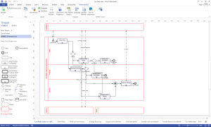
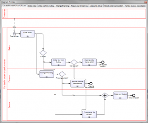
At this stage you may create a preview image of your model by clicking on the “Preview” button.
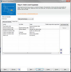
Step 4. Child-Level Expansion
Expand each top-level sub-process in a child-level diagram. Enumerate ten or fewer activities and possible end states. Then, for each activity, determine which one comes next. If an activity has multiple end states, define a target for each end state.
Child Level Activities
Child level: Select the activity, whose children you would like to edit.
Proceed analogously to Step 2 and Step 3 in order to define the child level activities and their paths.
Following the example:
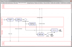
In step 4, steps 2 and 3 are repeated for each activity of the main process level. This is where the hard work starts. We will start by selecting the activity “Order car from factory” from the drop down.
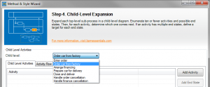
Similarly to step 2, we will create a list of the major child activities and their end states. These alternative end states will lead – directly or indirectly – to the end states of the parent activity defined earlier.
We assume that the activities “Receive production date” and “Confirm new delivery date” have two end states respectively.

This will result in the following sequence. If necessary, change the sequence as you did in step 3.
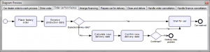
And here is the preview:
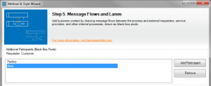
Step 5. Message Flows and Lanes
Add business context by drawing message flows between the process and external requesters, service providers, and other internal processes, drawn as black-box pools.
Additional Participants (Black-Box Pools)
List external requesters, service providers, and other internal processes. Use the ‘Add Participant’ button to define a new participant.
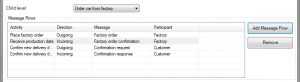
Child level: Select the activity, whose children you would like to edit.
Message Flow
- Add child activities involved in a collaboration by pressing the ‘Add Message Flow’ button.
- Select an entry and choose the involved activity from the drop down.
- Determine the direction of the message flow.
- In the ‘Message’ field, write the name of the message being sent or received.
- Use the drop down in the ‘Participant’ field to select the participant the activity is collaborating with.
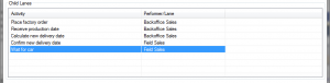
Child Lanes
For each child activity, define its performer (lane).
Following the example:
In step 5 we will be creating the collaboration model. In order to do that, we will define additional collaboration partners (participants).
As an example, we will look at the “Order car from factory” activity again. For each child activity you can define incoming and outgoing message flows.
If you wish, you may also define sub-lanes for each child activity at this point.
A preview of this sub-process will now give you the result below:
When you are done filling in all the information, you may create the Visio diagram by clicking on the “Create” button.