


Method & Style Wizard
The Method & Style Wizard will automatically generate a first diagram draft based on some user input, following the Method & Style rules defined by bpmessentials.com.
The aim of the wizard is to assist the process designer in the creation of a correct, consistent, appealing and unambiguous BPMN 2.0 model with the help of pointed questions. This concept and the basic method are introduced here in combination with an example.
General Usage
![]() : Saves the current Method&Style-values into a “.pmw” file.
: Saves the current Method&Style-values into a “.pmw” file.
![]() : Allows to open an already existing “.pmw” file from the filesystem or the repository
: Allows to open an already existing “.pmw” file from the filesystem or the repository
Reset: Clears all values and resets the wizard.
Preview: Generates a preview image of the diagram.
![]() : Brings the preview window to the front or re-opens it if it was closed. Only works if a diagram preview has previously been created.
: Brings the preview window to the front or re-opens it if it was closed. Only works if a diagram preview has previously been created.
Back: Takes you back to the previous step.
Next: Takes you to the next step.
Create: Creates a Visio diagram based on the collected information.
Cancel: Exits the wizard.
Help: Calls this help page.
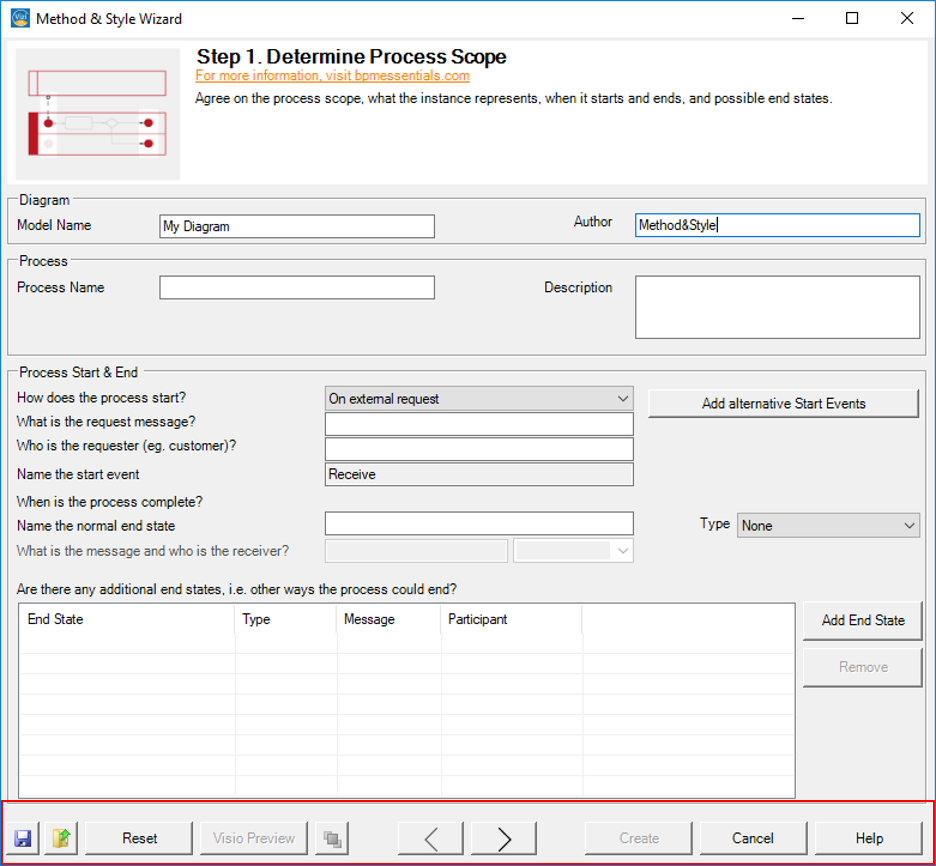
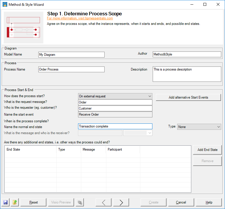
Step 1. Determine Process Scope
Agree on the process scope, what the instance represents, when it starts and ends, and possible end states.
Diagram
Model Name: Name your model.
Author: The author of the model.
Process
Process Name: Name your process, e.g. ‘Order Process’.
Descritption: A short description of the process.
Process Start & End
How does the process start? Choose between “on external request“, “on recurring schedule” or “manually by task performer”.
What is the request message? The request message, e.g. ‘Order’.
Who is the requester? Name the external requester, e.g. ‘Customer’.
Name the start event: Name the start event, e.g. ‘Weekly’ (recurring schedule), ‘Receive order’ (external request).
Name the normal end state: Name the normal, success end state. Use an adjective or a noun-adjective phrase, e.g. ‘Transaction complete’.
Add alternative Start events: List alternative and exception start events and open the list of all current start events.
List of additional end states: List alternative and exception end states, e.g. ‘Financing unavailable’, ‘Delivery date unacceptable’.
Step 2. The High-Level Map
Enumerate ten or fewer major activities in the high-level map. If the outcome of an activity affects the subsequent path, think about the end states of each activity.
Name the activities using verb-noun phrases, e.g. ‘Finalize order’.
Optionally, you may assign an activity to a performer.
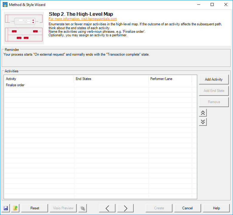
Activities
List major activities and, if necessary, define their possible end states.
- Click on ‘Add Activity’ to add a new activity.
- Select an activity and click on ‘Add End State’ to define the activity’s possible end states. Alternatively, click the ‘End States’ field of an activity.
- You may assign a performer by clicking the ‘Performer/Lane’ field and typing the name of the performer. Performers may be reused using the drop down menu.
Step 3. Top-Level Process Diagram
Create the top-level BPMN diagram. For each activity, determine which one comes next.
If an activity has multiple end states, define a target for each end state. A gateway will be drawn following the activity that tests the end states.
Mark the targets on which parallel flows need to be merged.
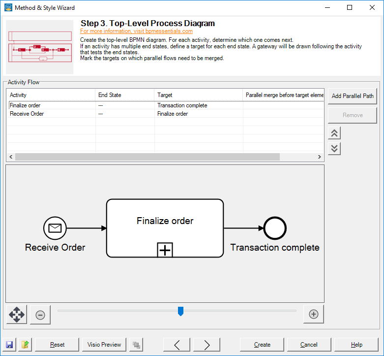
Activity Flow
For each activity, determine which one comes next:
- Choose an activity. If an activity has multiple end states, there will be multiple entries for the same activity with different end states.
- Based on the end state, select which activity comes next in the flow in the ‘Target’ field.
- You may add additional paths by clicking the ‘Add Path’ button. Use this to create parallel flows, for example.
- If the same target is used more than once, i.e. there are multiple paths that lead to the same target, specify if a parallel merge is needed on that target by ticking the column ‘Parallel merge on target?’.
- For easier readability, you may change the viewing order using the up & down arrows. This will have no effect on the actual path generation.
Step 4. Child-Level Expansion
Expand each top-level sub-process in a child-level diagram. Enumerate ten or fewer activities and possible end states. Then, for each activity, determine which one comes next. If an activity has multiple end states, define a target for each end state.

Child Level Activities
Child level: Select the activity, whose children you would like to edit.
Proceed analogously to Step 2 and Step 3 in order to define the child level activities and their paths.
Step 5. Message Flows and Lanes
Add business context by drawing message flows between the process and external requesters, service providers, and other internal processes, drawn as black-box pools.
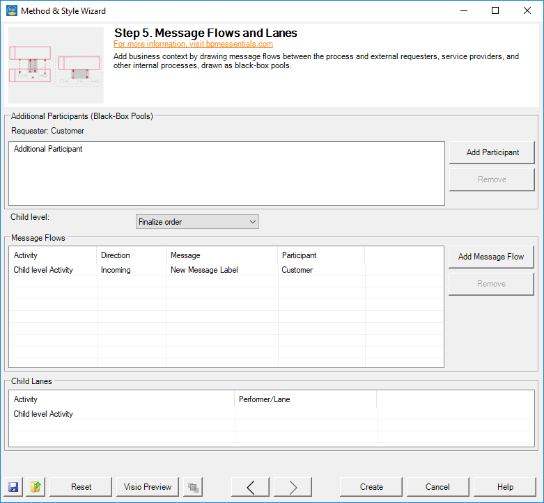
Additional Participants (Black-Box Pools)
List external requesters, service providers, and other internal processes. Use the ‘Add Participant’ button to define a new participant.
Child level: Select the activity, whose children you would like to edit.
Message Flow
- Add child activities involved in a collaboration by pressing the ‘Add Message Flow’ button.
- Select an entry and choose the involved activity from the drop down.
- Determine the direction of the message flow.
- In the ‘Message’ field, write the name of the message being sent or received.
- Use the drop down in the ‘Participant’ field to select the participant the activity is collaborating with.
Child Lanes
For each child activity, define its performer (lane).
Create
When you are done filling in all the information, you may create the Visio diagram by clicking on the “Create” button.